Need advice about cooling my tent

Agreed, but it would be good to measure my current airflow. That info would help me estimate how many more CFM are needed.

How do you determine where to place the marks on the card stock? How do you translate those marks into feet/minute?

I tested the effect of the warm exhaust from the tent on the “outside” temperature reported by the digital controller, which is attached to the tent. I started with everything but the ceiling fan off. Then, I turned the lights, exhaust fan, and circulating fan on full and let the temps stabilize. Results:

Starting: 74° inside tent; 75° outside.
Ending: 100° inside; 83° outside.

So the warm exhaust increased the room temp at the controller by 8°, which implies that piping the exhaust out a window would reduce both temperatures by the same amount. Comparison with my previous test, which ended with 100° inside and 84 - 86° at the controller, shows the ceiling fan had little, if any, effect on the temp at the controller or in the tent once the lights were turned on. We know already that I should lower the lights and dim them – that will reduce both temperatures. But now I know the reduction I could get by piping the exhaust outdoors.

I also tested the effect of the exhaust fan’s speed:

Inside Outside
Initial temps 77° 78°
Fan speed 7 101 83
Fan speed 5 104 83
Fan speed 3 109 84
Fan speed 7 101 83
Fan speed 10 99 83
Fan speed 7 100 83

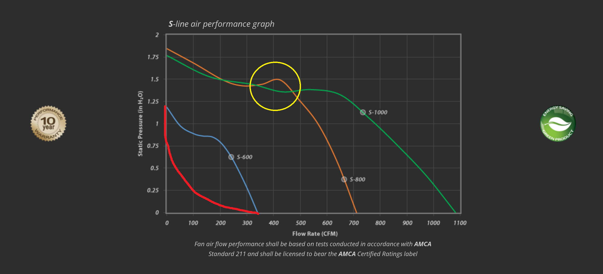
The fan speed had little, if any, effect on the outside readings. Increasing speed reduced the inside temp consistently throughout the range of speeds tested, but with diminishing returns: Speeds 3 & 5 differ by 5°, speeds 5 & 7 differ by 3°, and speeds 7 & 10 differ by only 1 or 2°. I suspect this nonlinearity is due to the filter. That is, the effect of its constriction is not a constant – it increases as the fan approaches the filter’s rated CFM.

In any case, the results suggest that @PhotoFinisH is correct: Increasing my system CFM would cool the tent further.

I doubt my wife would tolerate that, and I expect it would make the room hotter. Presently, the warm air can escape to the rest of the house (which has central air).

They’re wide open throughout the house. I doubt I could get a substantial increase without closing all the other 2nd floor registers, which you-know-who wouldn’t accept, even if I was willing.

I’d like to measure my CFM and am looking at instruments for that purpose. The propeller and hot-wire types look the most promising.

I would put a curtain rod up and hang curtains from the ceiling and use a portble a/c.

1 Like

When my mom was sick and i took care of her we moved her into her living room and divided with a curtain. She liked it hot in there.


2 Likes

Number two of my previous post. Tent exhausting into the room. It REALLY needs to be out of the room. The warmer air will just get recirculated if not.

One possible solution for the overall issue, is to use a dryer vent hose to connect to a lower exhaust port on the tent. And use cardboard to build a duct / register to sit over the a/c register. Basically pumping A/C directly into the tent.

Dual inline fans can be tricky, although it’s air, the turbulence is similar to the cavitation you’d see in a liquid. If the are not a matched set, it can cause premature failure of the fans. Again, more air won’t help, it needs to be cool air.

2 Likes

Are you dumping the exhaust air back into the lung room? It should be exhausted out of the room :love_you_gesture:

2 Likes

BTW, think about this. The house temp is as low as the tent temps can possibly be, more wind will not change temps, faster exchange will not change temps or at least will not drop it below house temps at best. Faster fans only brings in more of the same temps.

The mass of the lights, tent, plants, pots… everything in the tent is heat soaked. the temp of the air coming in has to overcome that… it will never get to house temps, as you’ve already seen with your test.

I know it doesn’t solve the current issue, but a lung room separate from the house temps is much easier to control, or using a closed system like the ACI unit.

For now, drop the house thermostat as low as you can tolerate, man up and tell the wife, it’s temporary, get over it.

“Shade tree” - “red neck engineer”… whatever… duct an a/c register to the tent. If you have any area in the house not be used consider covering the registers in those areas.

2 Likes

Well, only if the ambient air is cool enough to begin with.

The non-linearity is going to be something to do with perhaps the fan design itself at different power levels, &/or how the speed controller works. Any restriction from the carbon filter is going to be a constant, it’s just there, there it is.

Perhaps maybe. I know a couple people are saying that you should do this, & maybe you do need to. But I found that dumping back into my lung room worked better for me, after trying dumping into my basement. It didn’t help that my house thermostat is in there (in the lungroom), so the heat was running more often, it wasn’t a good setup for me. It was also more practical in terms of ‘setup & install’ to just dump back into the lung room after all. I would say every install should consider either option & see what makes more sense overall.

Probably just leave the hvac register settings alone then.

If you refer to the covering as a ‘tapestry’, she might let it slide. =) It would probably cause the room to heat up by itself, but if you add a window a/c in there or some sort of a/c in there one way or another, it would probably help it work better.

Based on the ambient air rising so much, it seems that the house aircon is not enough. You could try ducting from the house aircon register into the tent to see if that helps, but if it’s not cooling, then don’t be surprised if it starts producing humidity. You also have to worry about restrictions on the exhaust fan if you just hook that up as your only intake. Are you going to do that & have other intakes? You might try ducting the a/c to near your tent intake to see if that does any good at all. If not, I’d probably think about adding an a/c to the room somehow & would probably want to cover the archway, unless you do something like a closed-circuit camping a/c or something like that. That might be what you need to do in the end. Sorry to anyone who already suggested these things & I didn’t quote you, I am just agreeing.

I’ll reply again in a moment with some info on the swing gauge.

1 Like

You can probably flow your setup pretty easily in-place, you’ll just have to pull the carbon filter & do some temporary things. To make things easier you could add a short 4" diameter collar to the exhaust port & tape a stiff wire in place (red) to that to make your marks on. The green line is the swing paddle or whatever you want to call it. make that out of card stock & make the hinge out of tape.

There’s not too much to think about, but you want to set up the paddle so that it swings fully without much resistance from hanging down to going straight out. Now make sure its light enough for the fan to push it straight out when running at 100% power & nothing on the intake port (remove carbon filter), & also you’ll want to keep the tent door open to act as an ‘oversized intake port’ for these parts of the tests. Now add a little weight to the paddle until it sinks down maybe 1/4" from sticking straight out, & make your first mark on the stiff wire. You can call that your ‘max pressure’ mark. You weigh down the paddle until it sinks a little to be sure that the paddle will respond by sinking at the first sign of restrictions on the intake side. Now take a square piece of stiff material & block off 25% of the fans intake port, & make a mark on your wire, lined up with the end of the paddle. That is your 75% pressure mark. From here you’ll want to shut off the fan between adding restrictions, but now tape off 50% of the fans intake port turn it back on at 100% power (all of these tests will be made at 100% fan power) & make ‘your 50% pressure’ mark. Now tape off 75% of the fans intake port & make your ‘25% pressure’ mark. For the last couple the paddle is going to be farther away from the wire so you sort of have to eyeball where the end of the paddle is, over to the wire to make your mark. Your gauge is done, unless you want to work in 20% increments or 10%, etc. I think 25% should probably be enough to answer most questions, & probably the easiest to implement. One thing you also want to watch is to try & keep the fan & gauge at the same ‘level’ throughout testing, you don’t want to be tilting it around from where you start, or it will throw off the gauge.
Now remove all of the tape from the intake port & install the carbon filter, turn the fan back on, & see where the swing gauge ends up. If no restriction from the carbon filter, then it should be back around where the 100% pressure mark is. If restricted, then it should be somewhere below, & that will be how much energyyou are losing to the filter. On a fan performance chart I would consider it a percentage loss of pressure or negative pressure depending on the chart, but not necessarily a percentage loss of the max cfm. That might correlate with some fan designs, but not all. So based on the design of your fan, work off of a comparable flow map & work off of the pressure side & go from there to guesstimate what the actual cfm ends up, but you should be able to get close based on what is known about your fan & other fans, if you don’t have a pressure map for your exact make & model from the manufacturer.
From there you can decide to keep any restrictions or get a better-performing filter or pull it off to reduce/eliminate the restriction if needed. Either way the next step would be to dial in the intake area, & you would just seal up the tent & start adding intake area until your swing gauge makes it back to where it was when you tested the carbon filter, & if the carbon filter is not restrictive, then you’d be back to around your 100% pressure mark on the swing gauge. From there the only thing you’d want to do is slightly reduce the intake area in order to put a little bit of negative pressure on the tent to help keep the smell in, & also to increase the velocity at the intake area of the tent, at the expense of a little bit of cfm. This will help the air to plume into the tent instead of sticking to the walls which is what happens when the passive intake area becomes too big. No more cfm increase, just continuing to drop in velocity at the passive intakes, & the air starts to stick to the walls as it travels from the passive intakes to the exhaust fan. Any changes from your flowed setup & you would probably want to re-check the flow & adjust the intake area accordingly. Other than that, this doesn’t mean that you can’t run it a below 100% power, but you know that you’re getting the most for you power if you do. So doesn’t that mean that the intake area is too big if I dial it all in & then turn down the fan power? Well you’d be losing a little velocity at the intake area compared to at 100% power, but probably not enough to cause the flow to start sticking to the walls. If you dialed in in for max power, it should still work pretty well if you take a little power off. Anyway if the fan is sized properly & everything else is not causing too many issues, it should still be running closer to max rather than closer to min power I would think.

1 Like

I know I’m new to this but have you tried running the lights at night and them off during the day when it’s hotter?

2 Likes

Good idea, although in my case the curtain isn’t needed. Here’s what I’m thinking of:

Right. One of my previous tests (post 41) showed an 8° F increase in temperature at the digital controller due to the warm exhaust being returned to the room.

Agreed, although I’m not sure the room with the tent qualifies as a lung room. Does it?

That’s why I’m looking at portable ACs. Cheaper (in the long run, at least) than setting our HVAC thermostat to whatever’s needed to get the room down to 68° during late flowering. More comfortable and more considerate, wife-wise, too. I’ve learned to choose my battles. :crossed_swords:

Imagine blowing air through a narrow straw. You know from experience that it’s easy at low pressure, but as you increase the pressure, you hit the straw’s max CFM eventually. Beyond that point, you can blow as hard as you like but CFM can’t increase. In the present context, the filter’s max CFM sets the limit.

It sounds as though the DIY swing gauge gives relative measurements. That may be all that’s needed sometimes, but I think I need the actual air velocity (which is multiplied by the port area to get CFM).

That’s a good idea but, without the portable AC unit I’m thinking of, the room won’t be cool enough even at night, except in the winter. And I don’t want to grow only in winter, as @1LuckyMF does.

It seems that wisdom applies here, too. :+1:

I can’t end this post without reporting more test results. (I’m a scientist/engineer/researcher, professionally, so I can’t help myself).

I removed the carbon filter so the exhaust fan sucked air directly from the tent and blew it directly out an upper port – no ducting.

Inside Outside
Initial 74° 75°
Fan speed 7 100 84
Fan speed 10 98 83

Comparison with my results in post 41 shows that removing the filter reduced the temps at fan speeds 7 and 10 by 1°. At 10, I noticed the walls of the tent were beginning to be drawn in due to the negative pressure. I conclude that my filter isn’t costing me many CFM, but a larger fan would probably get the tent closer to the ambient temp. Might have to open a port at the bottom, though, so the fan can “breathe” better.

Finally, I tried uncovering the 2 windows at the front of the tent. They’re made of polypropylene, which transmits longwave IR (i.e., heat) quite well, so I was curious whether letting some of it escape would reduce the temp. It made no measurable difference

Right, let’s say that the carbon filter wouldn’t be a restriction with the fan running at lower power, but once the fan is trying to move more than the carbon filter can flow, it becomes a restriction. It’s acting the same way as an intake area that is too small for the fan at max power, but maybe not at a lower power. Hybrid fans don’t make pressure in a linear fashion as you add power &/r restriction, so maybe that had something to do with why you thought that the carbon filter isn’t a constant.

The thing about the diy swing gauge is at the very least, it will easily & cheaply show max flow, losses, & you can use it to see if you’re making things better or worse, & really that’s the best thing about it.
If you need to figure out your exact cfm, then measuring with the swing gauge vs pressure gauges or airspeed gauges should get you to around the same place in the end. Its more work with your fan since your manufacturer doesn’t give you a fan performance chart (pressure vs cfm) to work from, so you have to plot your pressure drops first & then see where you end up on a comparable performance chart in terms of percentage-loss of pressure after any restrictions, & where that puts you on the performance line, & where that spot lines up with the cfm portion of the chart. If you don’t have a flow map for your fan from the factory, then do equations or find a comparable map & work off of that. DIY swing gauge & a comparable map would probably be the least accurate, but it would have answered a lot of your questions a week ago well enough, without having to buy gauges & doing a lot of math. Not saying that your way would be wrong or not as good, but for quick, easy, & cheap answers that should be in the ballpark, a diy gauge & comparable performance chart (if not one from the factory) isn’t a bad way to do it.

PS I’d still check that filter to see what percent I’m losing to it.

1 Like

Yes, my to-do list includes getting an instrument to measure air velocity, lowering my lights so I can dim them and still provide adequate PPFD, and buying a portable AC. I’ll pick this thread up again when I’ve something to report.

Meanwhile, I say “thank you” to the many people who’ve devoted time to contributing observations and ideas. It’s very helpful to have experienced and knowledgeable people looking over my shoulder as I work toward getting my system set up properly.

PS - The nonlinear relation between fan speed and temperature reduction in my post #41 table is what would be expected if the airflow becomes turbulent. The drag (friction) that the air molecules experience is proportional with velocity at low flow rates and proportional with velocity squared when the flow transitions to turbulence. See this article.

I’m thinking that you were crossing through the flat spot on the performance curve, typical of hybrid centrifugal/axial fans. So at first, flow gains were high, then they tapered off, then started climbing again as you increased through the power settings. If you had a ‘true centrifugal’ blower, then the changes would probably look more linear, since that’s how their flow changes.

These are performance charts from Vortex Power Fans website, made at 100% power, & the changes in flow are are made by restricting the fan port. I guess they are testing vacuum on the intake port of the fan & blocking the exhaust, but same difference as checking pressure at the exhaust port & restricting the intake port.

Centrifugal: (My fan is the little blue line all the way to the left.)

Hybrid: (Ignore the red line, I drew that in there to represent one of those ‘helper fans’ & how their flow curves usually look. Also ignore yellow circle, I drew that in there trying to help someone else.)


But maybe you are right, & added turbulence at the intake area of the tent is helping the air mix better at higher power levels. Perhaps it’s a little combo of both ideas. It’s not important enough to argue over, it’s more important to try & minimize the restrictions & then dial in the intake area so you can get the most out of your fan for the least amount of power.

1 Like

I apologize if I’ve been argumentative. I find that discussions like this one are often informative – they’ve given me a better understanding of many subjects.

I’ve had trouble finding a definition for “hybrid” fan. The examples I’ve found run on a battery, in addition to 110 VAC. Is that what you mean by that term? Are pressure vs. CFM graphs for hybrids different from ones that run on AC only?

Your second figure shows a flat spot for all 3 units. Do you know what causes that? I doubt that it’s due to transitioning from laminar to turbulent flow because, if it was, the lines past the flat spots should show deceleration rather than (more or less) constant slopes. Here’s a graph of my table in post #41:

It resembles the red line you added to represent helper fans. What type of fans are they?

It occurred to me that the slight “tent sucking in” I noticed during my prior tests with the carbon filter removed is a sign that the rectangular ventilation port is restricting airflow. So – of course – I had to do another experiment.

After letting the temperatures stabilize in the previous, “no filter,” configuration, I opened the 2 circular ports on either side of the tent at the bottom:

Inside Outside
Initial 74 75
Fan speed 10 98 84
Speed 10 + 2 open ports 94 81

That change reduced the tent’s temp by 4°, so I’ll need more intake area to take full advantage of a bigger fan. Curiously, opening those 2 ports dropped the temp at the controller by 3° – not sure why.

I’m thinking I should jump to an 8" fan and filter. During my tests at lower fan speeds, I noticed that “air noise” decreased dramatically. So, with an 8" fan, I should be able to get all the CFM I need while producing less noise.

1 Like

You’re good bro, I didn’t think that we were arguing, just didn’t think that whatever caused that temp flux was really worth worrying about. To be fair to your idea, I’m kind of guessing on how a fan would plot on a performance chart with no restrictions but as the power increases from 0 to 100%, vs. running them at 100% power & going from 0 to 100% restriction. Usually most performance charts have the fan at 100% power & then vary the restriction, so again I’m sort of guessing on how it would plot when varying the power & no restrictions. =)

Hybrid vs. Centrifugal vs. Radial vs. Axial - most of the differences between those fan names are in the design of the fan blades & the fan housing. Something like a computer fan or the booster/ helper fan is an axial design, that’s what I was trying to draw with the red line. (I see that it says centrifugal in the ad in the link above, but it’s not really a real centrifugal blower). Axials usually can’t make a lot of pressure, & flow starts to fall off quickly as restrictions build. Something like a Vortex vtx400 is a real centrifugal blower. Something like what you have in the S4 or the Vortex S-Line is a hybrid design of an axial & centrifugal blower design. If you compare the flow maps you might find some true centrifugals can out-flow even a larger hybrid, when really loaded with restrictions. So if you have an application with a lot of unavoidable restrictions, then a true centrifugal might be better than a hybrid. But a same-sized hybrid as the centrifugal can probably outflow the centrifugal at lower restriction levels for around the same power, so if you can have a setup with a low amount of restrictions, then the hybrid might be better than the true centrifugal.

Also the hybrids are a newer design & usually have more advanced pcm motors compared to the older true centrifugal designs.

I really don’t know why exactly the true centrifugal fans have a more linear response as restrictions build, as compared to the hybrid fans. But it probably goes back to the blade design & housing design. If you dig a little more, you’ll find different blade types even within the fan types, & they’re probably all going to flow a little differently on the flow maps. For the centrifugals usually you’ll see straight, or concave, or convex blades. I’m not sure what my vtx400 has, probably concave. For the hybrids, it’s probably more complex in terms of different blade setups, but you’ll see the axial & centrifugal blade stages set up differently, etc. searching for pics. But from what I’ve seen in general, the true centrifugals seem to have that more linear diagonal response to pressure on the maps, & the hybrids have that plateau or some sort of non-linear response on the maps. The axial type helper fans may as well just drop off to nothing at the first sign of restriction.

Yeah you might need to go to a more powerful fan & probably in any case a bigger filter that can flow more & still be effective at odor control, but you’re right, the tent sucking in is the fan telling you that it can flow more, & you just need to let it eat. So far you’ve pointed out two flow restrictions. The restriction caused by the carbon filter since the tent went from not sucking in to sucking in after you removed it, & then the restriction caused by the too-small intake area causing the tent to suck in. The only thing you’d want to check for is you don’t want to go to ‘too much intake area’ - then you just lose velocity at the intake ports for no more CFM.

Running the fan at a lower speed than 100% is fine. Nothing wrong with that. But the flow testing & dialing in of everything is usually done at 100% power. Not sure if I would get too caught up in initial testing or what happens at different fan speeds, until it’s dialed for 100% fan speed. Then you can tune it for a slower speed if needed. Basically if you flow it for 100% & then want to turn it down, you might need to also go back & slightly reduce the intake area of the tent to keep the velocity a little higher at the intake area of the tent, that’d be about it. You’d still be able to do pretty much all of this on a diy swing gauge, or you could buy gauges. Or you could try to read the tent sucking in vs. when it stops, but that’s the least accurate probably.

1 Like

Aha. An alternative term I’m finding is “mixed flow” fan, which refers to the impeller design. Apparently, the impeller gives the fan characteristics of axial and centrifugal designs.

Those Vortex S series fans are nice but pricey – $360 for a 6" rated at 344 CFM.

I think that amounts to “balancing” the system, with a bias toward creating slightly lower pressure in the tent. Why would the resulting higher air velocity at the intake benefit the plants? I have a 6" oscillating fan and each of my lights has a fan at its center that blows down, so I’d think my circulation is adequate.

The curious drop in outside temperature I reported after I opened the two ports resulted from misreading my notes. It remained at 81°. The inside/outside temps after the system cooled down were 75/74, so the reduced inside temp wasn’t due to the room cooling down during the test.

I’ve realized that the nonlinearity in my graph has a mundane explanation. Suppose a fan draws a volume of air from a tent every minute that’s equal to the tent’s volume. That yields an exchange rate of once per minute, but it doesn’t mean all the old air is replaced with new every minute. Circulation in the tent (much of it created deliberately) prevents that.

Suppose half of the old air molecules are replaced each minute. After minute one, 50% of the old molecules remain in the tent. After minute two, 25% remain, and so on. This leads directly to the negative exponential function evident in my graph.

1 Like

OK I’ve heard that too, ‘mixed flow’. I’m not trying to sell you a Vortex, but I know that Vortex publishes ‘pressure vs. flow’ maps, so that’s mainly why I’m referring to them. Plus I do run a couple. If AC Infinity published them for their stuff, we’d probably be looking at one for your exact fan instead! ACI does iirc publish a max cfm & a max pressure number at least, for most of their fans. (Also max power draw is good to look at in any case.)

OK ‘balancing’, ‘tuning’, etc. the intake area to hit the sweet spot …


… is going to be just under ‘max cfm’, to keep a little negative pressure (green line on chart above) on the tent, & it also will keep a little velocity at the intake ports of the tent. You’re trading velocity (also green line in chart above) for cfm (blue line) as soon as you start opening & increasing the tents intake area (black line). Once the intake is as big as it needs to be, you’re at max cfm but down on velocity. If you keep adding intake area you gain no more cfm but continue to lose velocity, eventually the air just runs along the walls to the exhaust. You also lose that negative pressure. Better to dial in the intake area to where it’s just under max cfm, & you’re trading that last bit of cfm for a bit of negative pressure & also a little more velocity at the intake of the tent to help it plume into the space, instead of sticking to the walls on its way to the exhaust if the intake area is too big. But I would agree that you probably also want the circulation fans in the tent as well. The only thing here is that we don’t really know how much actual flow you need yet. You might be able to run the 4", or you might need a 6" or 8". If you’re getting an air conditioner, maybe set that up & then re-evaluate what the 4" can do, & then go from there.

1 Like

And not just for the exhaust fan. It’s good to determine the entire system’s power requirement so a need for a 2nd AC circuit doesn’t come as a rude surprise. A portable AC, for example, is apt to need more power than all the other devices combined.

The visual image I got from your description communicated the value of maintaining velocity at the intake very clearly. I see that your DIY swing gauge is a balance indicator and, for many purposes, that’s all that’s needed. I can go more low-tech, though: Lick your finger and see if you can discern any airflow at the intake. :cowboy_hat_face:

My thoughts, too. The AC should make it much easier for the exhaust fan to maintain the desired tent temperature, so maybe my 4" and filter are adequate.

One AC unit I’m looking at has a remote control that can report its temp to the unit, in place of the unit’s internal sensor. If the remote is placed in the tent, the exhaust fan can run at a constant speed, providing a stable exchange rate, while the AC maintains the desired temp. Adding an AC unit like this relieves the exhaust fan of cooling duty, so it need only provide the desired airflow.

I wanted to look up the differences in blade types within the true centrifugal style fans, & this link is pretty good:
Blade Types Link

After reading that, now I’m thinking that my vtx fan probably doesn’t have forwards inclined blades like I said, just based on the difference in pressure curves. I can look that up or check it. I seem to remember them being curved & just assumed that they spun scooping into the air. But mainly after seeing those charts, I was thinking that maybe the mixed flow/ hybrids like the s-line & the s4 do use the forward curved blades, & that helps create their curves with the flat spot, in addition to the axial stage contributing to it as well. Not that important, just thought it was some interesting info.

The other thing I was wondering about, is, do you think if you ran a more powerful fan like an s6 & flowed it for max flow, do you think that it would be enough to avoid having to buy an air conditioner?

1 Like