@Audiofreak: I’ve got a T3 now and am curious: If you have it outside your tent, do you pipe the water vapor to a bottom or a top port? If it’s inside, is it on the floor or elevated? I’m unsure which is better.
Not sure as too better but mine is inside on floor. Under net.
I’ll have 4 plants and won’t have room inside. I’ll pipe through one of the ports for electrical cords at the bottom. Thanks again for your help. ![]()
Maybe not, but you can always try it without it first, & then you can add it if needed. It’s probably getting cooler these days so you might not be able to really check again until next year! When you’re referring to temps ‘at the controller’, I was wondering where your temp sensor itself is.
Are you still planning on doing any flow work?
Wondering if you started to think of going with a pressure/vac combo gauge instead of an airspeed gauge, or what. You could still do a diy swing gauge for a quick ‘bench test’ & to see what you’re losing to the filter, & to dial in your intake area. Might help to work out things like why closing some of your intake area helped your temp numbers. (Unless I was misunderstanding that, but I thought I read something like that earlier.) You might have had too much intake area for what the fan was capable of pulling, & losing too much velocity at the intake areas, so the flow was just rolling along the walls mostly, instead of pluming into the tent more. Could have also been due to those intakes being too high up, but it wasn’t exactly clear to me where they were located. But if you have too much intake area overall, you can check for that with the swing gauge.
The controller – which has internal temp and humidity sensors – is attached to the front of the tent. Its remote temp & humidity sensor is hanging inside.
Yes, I’m keen to do airspeed measurements as soon as the Testo 405i hot-wire anemometer I’ve ordered arrives, probably on Wed. If I decide to pipe the air outside, I’ll use a 6" hose. That should reduce airflow losses caused by bends in the hose. It’s also the only size that fits any of the window kits I’ve seen. I found a 6" to 4" adapter, so I can start by testing my 4" inline fan. If it’s inadequate, I’ll substitute a 6" fan.
If I find that my 4" filter is costing too much airflow, or I switch to a 6" fan, I think I’ll buy an 8" filter and use an adapter to fit it to the fan.
My table in post#55 (14-Aug) shows that opening 2 circular ports at the bottom of the tent decreased the inside temp by 4°. The table also shows the outside temp decreased, but that’s a typo. The outside temp was 81° before and after opening the additional ports.
Got it.
Sounds logical.
Got it. I’ll be more tuned-in once we have some flow numbers to work from.
Still thinking airspeed might not be the easiest way to do it. Also still wondering how you plan to solve for an intake area that can’t easily be measured. Don’t you have to plug that in to the equation? How would you account for the ‘intake area’ of a restrictive carbon filter? Or do you plan to just work off of percentage-loss at that point? To be fair if you switched to a pressure/vac combo gauge you would still have to know/do that to convert to cfm if that’s all you had, but you could also take that psi/vac reading directly to a fan performance chart if the manufacturer provides one, or take it to a comparable fan performance chart. Usually most of the fan performance charts that I see from manufacturers are pressure/vacuum vs. CFM , so if you pull that number directly with the gauge you can sidestep the problem of having to convert & having to account for the ‘intake area’ of a restrictive carbon filter or any restriction/ intake area that is tough to account for. Of course, you could also first dial in the intake area to the unrestricted exhaust fan, & then install & flow-test carbon filters until you have one that equals the flow rate of the tuned intake area, & then at least you know you can just plug in that intake area of the tent, if you have to do the math. I still think that a DIY swing gauge would be fine for all of this & the quickest cheapest easiest - not the most accurate, but good enough. But also thinking that if you want to do a gauge with numbers on it, to do a pressure/vac combo gauge instead of the hot-wire airspeed indicator. Any reasons you didn’t want to do a DIY swing gauge, or a pressure/vac combo gauge?
I chose an anemometer because it’s easy to use and gives a direct numerical measurement of air velocity, which converts easily to CFM. Testo states the 405i has an accuracy of ±5%, which is sufficient for my purposes.
I also like the fact that it’s only a probe with a Bluetooth transmitter that interfaces with an app on your phone. That design eliminates the cost of electronics that would be needed otherwise, so they can provide a better sensor for the price.
For the inline fan, I need only measure average outlet velocity with the filter in place and removed. The ratio will tell me the %CFM the filter costs. Actual CFMs can be computed using the area of the fan’s 4" outlet port.
The air inlet measures 6" x 12" and I’ll measure the average velocity there, too. Converting to CFM should yield the same value I measure at the fan’s outlet. It’s a worthwhile reality check.
If the inlet velocity is too low, I can increase it by reducing the port’s area and can easily measure the effect on the fan’s output.
If you just want to compare the difference between the bench test & then with the filter installed, a swing gauge will get you to the same place.
But to get the actual CFMs using the equation to convert airspeed to cfm, don’t you have to provide the intake area as well as the exhaust area? Maybe I’m misremembering. Can you post the equation again & list out what each thing represents again? I was thinking that you can plug in 4" for both ports if you’re just bench testing the fan alone with no restrictions, but if the carbon filter is installed & is restrictive, then the ‘intake area’ would be made up of the free space across surface of the carbon element, no? & if it’s restrictive, the best you could say without being able to measure that is 'less than 4" ', I guess. If you record air pressure/vacuum, at least then you can take your readings to the performance chart & it’ll tell you the cfms directly that way, avoiding having to worry about the intake area across the carbon.
One other thought is that with a swing gauge or a pressure gauge, it’s going to give you the average or max readings without having to take readings from more than one location across the port. You are probably going to see different airspeeds depending on where you have the probe in relation to the port, at the center vs. at the edge for example, so you’ll have to take multiple readings & work out an average. Unless during the initial bench test you figure out where to park it & get the factory claimed max rated flow number as the answer to your equation. But seems like with the swing gauge or a pressure gauge, it would be more consistent & direct to get your answers.
Thinking some more about the airspeed sensor & simplification & practicality of dialing in flow, & since I believe that there are published max cfm & max pressure ratings for your fan (no map unfortunately), I think you can just throw out the conversion math & just get any constant number from the sensor with an initial bench test (fan at full power & no restrictions on either side, & the sensor always in the same location), & ideally just try to keep the number there after you install the fan into the tent & as you add any further pieces to the vent system, & finally dial in the intake.
And during the initial bench test you could still block off the fan intake in 25% increments & get readings from the air sensor ( still always in the same location) to make a performance chart & be able to see any losses as a percentage loss of flow without having to do a lot of math. Does that sound good or not?
percentage loss of flow should be percentage gain of pressure, oops. Trying to make this less confusing, sorry.
CFM = V x A ,
where V is the average air velocity in feet/minute and A is the area in square feet of the opening through which the air passes. So, if air is moving through a 4" round opening at an avg velocity of 2291 feet/minute:
CFM = 2291 * π * (2/12)^2 = 200 cubic feet/minute
Uh…no. Surface area (A) of a cylinder:
A = 2π r(h+r) ,
where r is the cylinder’s radius and h is its height. That’s obviously >> than 4 square inches for my filter. But I don’t see the relevance.
Definitely. I think that’s why every anemometer I’ve looked at (on Amazon) has an averaging function.
My fan’s max rated CFM is 195. Don’t know max pressure. (It’s a Vivosun Aerozesh G4.)
That would be interesting, but I don’t understand how it would be helpful. Seems to me that the main measurement I need is the CFM I’m getting with the filter in place. (And, as a point of interest, CFM without the filter, so I know how restrictive it is.)
Measuring CFM at several fan speeds will enable me to graph tent temp and humidity as a function of CFM. If my airflow is inadequate, I can estimate how much I need by extrapolating the graph. I can also judge the efficacy of the humidifier I’ve added.
It’s going to be less than the surface area of the cylinder, it’s more like the surface area of the holes in the material of the cylinders & the free area between & through the layer of carbon. Somewhere in there one will be the limiting factor. But I was overthinking the process & you don’t really need to use the equation at that point. But there’s either going to be enough area there to not be a restriction, or less. So if it’s a restriction, it could be a total of less area than the 4" intake area, is what I was thinking.
Ahh, OK, I thought you had an ACInfinity S4 for some reason. I’ll have to check out the stats for yours & see what they say.
This is probably the first thing I would do, ‘bench test’ the fan at 100% power & no restrictions, then measure again at 25%, 50%, & 75% restricted intake port (you can do it installed, just unhook the carbon filter, & leave the door open to ensure enough ‘intake area’), because doing this gives you four numbers to plot on your ‘DIY performance chart’, analogous to 0% 25% 50% & 75% pressure gain. Run the equation for each one & plot the CFM. Then as you build your system & check your readings for flow changes as you go, you’ll be able to more quickly see where you are on your chart & should be able to do less/ less complicated math overall. You could bench test at smaller increments but it seems easiest to block off the intake at 25% increments, & should be a good- enough reference for initially detecting changes.
Once you get the tent set up & the flow in the sweet spot at 100% power, then you can experiment with reducing fan power (& likely intake area as you reduce power, to stay in the sweet spot). But initially you want to dial in your flow & plot a performance chart at max power first in order to know what it needs to get there, if it’s enough for your setup in the first place, or if there is more to do. Also usually fan performance charts are made at 100% power & they vary the restriction, which makes sense since we know from earlier that the response to power is linear, but response to restriction at 100% power may not be.
Good point. I see now that you were addressing the “effective” surface area, which would have to account for friction caused by the pre-filter sock and carbon granules, too.
Probably because I have AC’s refillable 4" filter. (“Refillable” appeals to my sense of thrift and wish to minimize my contributions to the local landfill.)
I see. Once I have the graph, I can estimate the system’s aggregate restriction by measuring CFM at the fan’s exhaust port.
50% restriction is easy to produce; 25% and 75% are trickier because the port is round. But they’re do-able.
That reminds me: Do you know how manufacturers determine CFM ratings for their filters? My guess is they connect the filter to a powerful fan and increase its RPM until CFM at the outlet stops increasing.
Got around to looking at the fan on the factory site. There’s a good drawing of both sets of fan blades if you scroll down. (Not sure why they wouldn’t put that pic up with the other highlighted main ones. I started looking at the main ones & started thinking it only had an axial blade set.) I see they list a max CFM, no performance chart or at least max pressure, but you should be able to work off of your airspeed indicator & math to get your cfm & check for losses.
“Effective surface area”, that sounds like a much better way of saying what I was trying to say. You should be able to work around having to measure any of the actual surface area there, just measure well elsewhere. I was overthinking it.
I used a 90deg corner piece of 1/2" foamboard insulation for the 25% obstruction, & just made sure to have it centered, & taped it to keep it square & from getting sucked inwards. I used packing tape for 50% & 75% obstruction & thought it was ok, but you could do something else. It’s not really necessary - but another good reason to do it is to ‘shake down’ the gauge, check the math, see if everything is working as expected, etc. If so, then plot the data as your performance chart, just have the airspeed instead of the pressure/ vacuum. I would expect the airspeed to fall as cfm rises, but maybe I could be wrong about that. But I think that’s what that would look like. If not I’ll be confused.
One thing I thought of is I believe that you’ll want to adjust the intake area number in the math for each 25% reduction across the intake port when doing the initial bench test. But easy enough to calculate all of that, starting with the area of the circle of the fan port & going from there.
I’m not exactly sure how the official ansi flow tests work, but I believe that they use a manometer to check the pressure & vacuum. I was thinking I could use some air pressure gauges to check it, but pretty sure a manometer is what I needed to remember. Either way you can get to CFM & check for losses with the math & either the anen- or the man- ometer. My guess is that the official tests for the filters would pre-set the minimum/maximum specs for each fan used at each specific port size, & that they would run that test for the filter with the fan at 100% power, so that the manufacturer/ designer can work on the filter before getting official certifications.
Have you made any progress with making a flow map for your fan &/or other flow testing?
Sorry – I’ve been sidetracked.
I removed the filter from my fan and took readings. I tried to move the probe around in the fan’s ducts so I sampled the entire area. (Have to be careful not to hit the blades at the inlet. The outlet has a perforated guard that prevents that problem.)
Inlet:

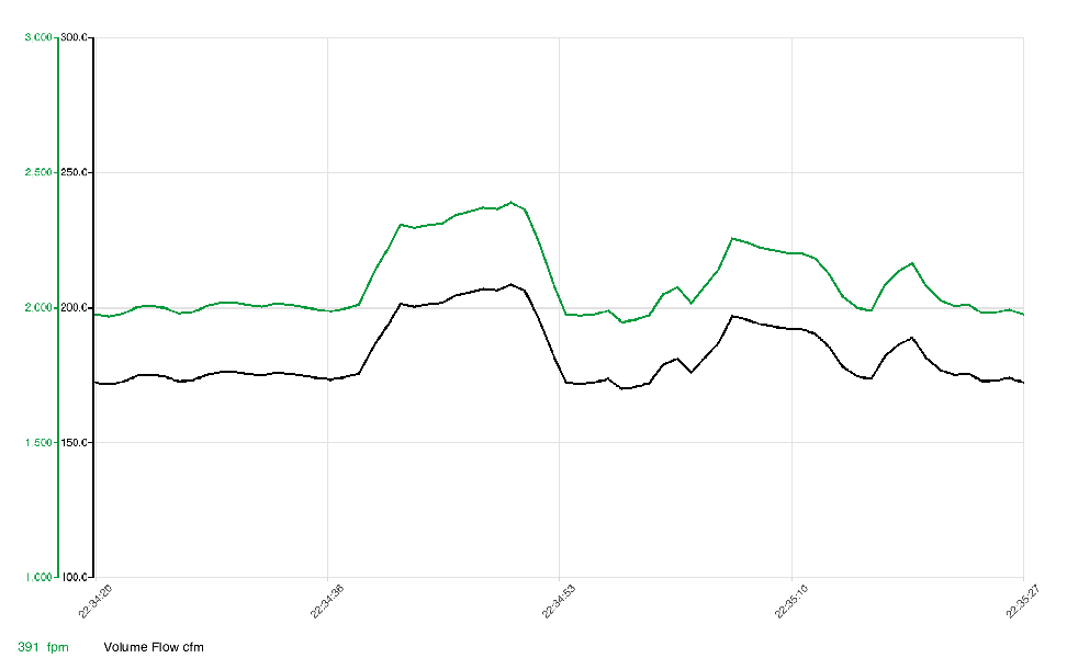
Outlet:

The green lines are air velocity (FPM) and the black lines are airflow (CFM).
Obviously, my results make no sense. The highest airflow reading at the inlet was 24 and the highest at the outlet was 97. And 97 is less than half the fan’s rated airflow (195).
I need to spend more time with the probe so I can learn how to get plausible and repeatable measurements.
Hmm not sure what to make of that. Not sure you want to be sticking the probe inside of the ducting, more like move it across the plane of the opening of the exit port. You could try sticking a short straight 4" diameter tube, like 3" to 4" long, on the exhaust to ‘sculpt’ the air flow leaving the fan a little, & take readings across the plane of the opening, I guess from the center to the edge in a straight line in order to get the average, & that might smooth out the readings a little.
I’d say keep trying to learn the meter. However if you want some quick data now that I can interpret more easily, you can still just do a swing gauge & that I can easily understand how to set up & read it. This might be one of the last warmer weeks of the year to do some good testing until next summer.
![]()
I have one 200w light in a 2x4 tent and it produces extremely well. IMHO you are using to much light. I have never ran mine at 100% either.
This should give you a chuckle. Here are two photos of the sensor end of the probe:


The photo on the right shows what happens when the user discovers that the probe has a built-in protective cover that must be rotated to the open position to obtain correct measurements. (Apparently, deemed too obvious to mention in the manual.)
I’m not using any light at the moment, but I do have the ability to produce more than most people believe is needed, esp. without CO2.
Here’s the graph for the fan’s exhaust side without the carbon filter. In this and subsequent figures, I started at the duct’s center with the probe flush with the duct, then moved to the bottom, top, left, and right. Black is CFM; green is FPM:
The values range from 170 - 209 CFM and average 183.
Exhaust with filter:

The values range from 63 - 117 CFM and average 95. That means the filter cuts the fan’s output by roughly 50% (!)
Here are measurements taken at a spot near the filter’s fan side, followed by a spot furthest from the fan:

CFM at the rear is about 70% of that nearest the fan. That means the practice of reversing the filter to get more life from it probably works, but not for long.
I’ll do measurements with the tent zipped up next.
Heh, yeah that is funny man. Glad you got it working & starting to show some data. Not really surprised that the filter is taking so much, but at least you know where to start if you need more flow out of your current fan. The only thing I’m thinking about is that the airspeed dropped with the restriction, & I was thinking it might increase. But maybe that is happening elsewhere within the fan housing &/or between the filter & the fan intake. Just thinking of for example kinking a garden hose, the water volume decreases but the velocity increases coming out of the hose. It’s not important, just my own wonderings.